Raspberry PI and OctoPrint

3D Printing, Electronics

Note: I had originally planned on posting this one after I had assembled my 3D printer but as it appears it’s going to be a while (FedEx has been waiting for it to be dropped off for a week in Hong Kong, don’t think it’s gonna make it to the US by it’s scheduled delivery Monday)

One of the things I wanted to do right away with my 3D printer is to make it a little bit smarter which is where OctoPrint comes in which is a nice piece of software that gives your 3D printer a web interface for management. With Raspberry Pi’s as cheap as they are it makes the OctoPi version a no-brainer.

In addition to a web-cam via the Raspberry Pi Camera Module the Pi’s GPIO pins for a filament run-out sensor and a relay to cut the power to be able to cut power to the printer through the Pi, even remotely.

Filament Sensor

For the filament sensor I found an inexpensive optical endstop sensor (can be found many places, just included Amazon link as an example) and then printed a housing for it. I went with this one as it includes mounts for my printer, but this one is much simpler if you don’t need a mount or want to design your own mount.

OctoPrint has an plugin called Filament Sensor which has instructions for configuring it. The sensor I got came with three pins labeled V, S, and G and absolutely no documentation so I guessed that G was ground, S was signal, and V voltage in. With that highly scientific deduction done I plugged V into one of the 3.3v pins, G into one of the ground points, and S to one of the GPIO pins. I chose GPIO24 as it was near both a 3.3v pin and a ground. Some testing found this appears to work so now I just need the printer so I can print the housing… and use it.

Power Relay

I got a dual relay board (getting the module instead of just two relays for cleaner wiring and mounting. One relay is for turning power on and off to the printer power supply and the other will be used later as a switch for some lighting for the print bed. I used this as a guide for wiring up the relays and configuring them in OctoPrint.

For wiring there were two sets of pins on my relay board. I relied on the internet on this one as I didn’t fully understand it but it seems to work. On the left side was JD-VCC which I wired to 5V, VCC which was wired to 3.3V and GND to ground. The other set of pins had GND (which had a trace to other GND so we don’t need to bother with it), IN1 which I wired to GPIO17, IN2 wired to GPIO18, and finally VCC I wired to another 5V pin.

I’ll defer to this documentation on configuring OctoPrint to have options to flip these relays. Make sure you change /etc/init.d/octoprint and ~/.octoprint/config.yaml. Also make sure you use a relay that can handle the power as for this purpose I’ll be running straight mains power through it.

Nice Hat

So I got it all working and even wired up an RGB LED that I have some ideas for future work but it’s kind of a mess and if anything gets unplugged it’s gonna be a hassle to make sure I have the right pins.  What I need is a hat… no seriously that’s what they are called (no I don’t know why). Basically it’s a board that can stack on a Raspberry Pi and provider an expanded interface for the GPIO pins. I picked a cheap one that came with support standoffs (I got this one) and wired it up so it was a little easier to hookup and disconnect as needed. I used some multicolored jumper wires to create cables for each of my purposes and used coloring to make sure I know where things plug in later.

Now all I need is a printer to finish this stuff off!

Living Images

Electronics, Trains

A feature that’s been available on select Nokia Windows Phones for a while is called living images. The general idea is that it takes a 2-3 second snippet of video and combines that with some subtle image effects to create a 6 second “Video”. Unfortunately I was unable to figure out how this worked and it really only would play back on the phone and I couldn’t find a way to export the video. If I copied the image file over it’d just be a static jpeg.

Things changed recently as I have upgraded my phone to a preview of Windows 10 and discovered pictures I uploaded to my Windows 10 computer were doing the animation. This prompted me to figure out how it’s done. Turns out there is two ways, in Windows Phone 8 there are a pair of special hidden files (that don’t auto sync to the computer or one drive). One of them is a MP4 file (the one that ends with .mp4.thm). With Windows 10 it’s embedded in the jpeg itself (which I’m still looking into how they do this). I found a way on the phone to extract the video portion from these Windows 10 images as an mp4.

You may be wondering what this has to do with trains, and so far technically nothing but I was able to take a couple of the pictures from the last operating session and extract the video files and use an mp4 to animated gif converter and create these:

Yard Limits.gif

Yard Limits

DMIR210_400Club.gif

400 Club

Approaching bridge.gif

Bridge Approach

Not sure how much I’m going to use these moving forward and certainly welcoming any feedback . I will note the stop of motion and color change with slow zoom at the halfway point is something the camera does as part of the living images and I experimented with removing it but it just made it too short and jarring when it restarts.

Note:  After publishing this I discovered it takes a while to start working properly in MS Edge (and probably IE too). If the images aren’t moving, or are moving very slowly just wait (or try Google Chrome). No idea if FireFox works but it’s likely better than Edge/IE

Attempted JMR-Pi

Electronics, Trains

A couple of days ago I got the idea to install JMRI on my Raspberry Pi, and even found a script that’s supposed to automate it.

Unfortunately it appears that script was last updated in 2013 and is not entirely working (it’s bombing out starting VNC). I think I will have to table this project unless I can find someone that can help. I’m certainly not a Linux expert and I’m feel like I’m wasting time that could be spent working on other things.

On the plus side I was able to get all my feeders soldered now I just need to do a double check that there aren’t already any shorts and start on the bus.

Electronics Project

Electronics, Trains

This summer I backed a kickstarter for a small microprocessor called the Digispark Pro (I believe based on the ATTiny85). You can find the completed kickstarter here, and where you can get it now here. As a reward for my backing I got a Digispark Pro and a couple shields designed to fit on it. One of those is a shield with basically this OLED display (what I got doesn’t appear to have made it to the digistump store yet).

digispark pro

I recall having an idea of what I was going to use it for when I initially backed it but have since forgotten what it was. In the mean time I’ve come up with a couple of railroad related ideas what to do both based on using something like Model Railroading with Arduino which is an Arduino library for connecting to Digitrax Loconet.

The first idea was to use a Bluetooth Low Energy receiver to use it as a bridge for custom wireless throttles either using another microprocessor and BLE radio or with a cellphone app.

The second idea is to use the same library and the OLED display to show data from the loconet bus such as either the fast clock or status information. Since I don’t have any BLE stuff I’ll start with this idea and see how it goes

Blog Organization Updates

Electronics, Trains

I’ve been doing some cleanup and updates to the categorization of posts with one important purpose in mind. As part of my playing with electronics I’ve developed as a sometimes intertwined additional hobby. I wanted to start blogging some of my electronic exploits but didn’t want to start a new blog.

On the other hand this blog was originally started as a model railroading blog and I didn’t want to alienate any readers that came here for the trains but don’t care about the electronics. To do this I’m changing how I use the WordPress categories. I’ve retroactively updated previous posts and from now on I’ll be tagging posts with a Train or Electronics (or both) category.

This makes the two new menu links work (Train and Electronics next to Home), they allow you to see only the posts related to that category and gives them separate RSS feed if you use something like Feedly (there is  a link on each page). But really you only have to care about those if you aren’t interested in everything.

Crossing Flasher update

Electronics, Trains

A while ago received an Amazon.com gift certificate, it wasn’t a lot but it turns out you can get a lot of inexpensive electronic components from re-sellers (the ones in particular I bought from were based in China). Part of my order came in (it takes a long time for things to ship from China evidently) which spurred me to pull out my crossing flasher project to continue some work.

The parts I received were servos, I’m going to try to only use one but I’ve got two just in case I can’t make the rigging work. Fortunately servos are pretty easy to control with an Arduino but I came to the conclusion I needed to solve for sound before I finalized pin assignments for the lights, and servos, and sensors.

I finally decided on an Adafruit arduino shield that has an SD card reader and can play simple mono wave files (it’s a bell, doesn’t need anything complex). Even better its available as a kit! -> https://www.adafruit.com/products/94

WP_20140619_19_03_40_Pro

Since I was making an order I decided to upgrade my soldering iron to one a bit better than the cheapy radio shack one which ended up being a great purchase!

WP_20140619_21_43_55_Pro

I actually got it assembled last week but didn’t get time to test it till tonight (which it worked, yay I’m not incompetent and following directions).

With this working I need to start figure out pin assignments and start prototyping the servo and sensor control before wiring it all up!

Flasher Light Circuit Version 1 Completed

Electronics, Trains

WP_20140209_12_24_54_Pro

I got my light circuit completed, it’s fairly simple and doesn’t do much other than host the appropriate resistors and transistors. It get’s four lines from the Arduino: 5V, GND, and Digital Pins 12 & 13. The flasher lights are common cathode so the 5V goes straight to the lights. To control the flashing I use the transistors, when I apply power to the transistor via one of the digital pins which connects the ground on the lights. In essence the transistor is acting as a solid state relay.

After this I started working on activating the lights, I’m looking to do a couple of options for redundancy. It seems that the time things like this don’t work is when you are at a show or showing somebody so I want to start with a push button that can be used to toggle it on and off.

WP_20140209_13_21_52_Pro

It’s basically just a simple normally open push button hooked up to Digital Pin 2, the only complicated bit is the debounce to prevent weird behavior. I basically took the Arduino Debounce tutorial (http://arduino.cc/en/Tutorial/Debounce) for this. Next up I’m going to work on using a couple of light sensors as another way to activate them.

Current state of the code:

const int ledRight = 13;
const int ledLeft = 12;
const int btnOverride = 2;

int ledState = LOW;
long previousMillis = 0;
int flasherState = LOW;

long interval = 500;

int buttonState;             // the current reading from the input pin
int lastButtonState = LOW;   // the previous reading from the input pin

// the following variables are long's because the time, measured in miliseconds,
// will quickly become a bigger number than can be stored in an int.
long lastDebounceTime = 0;  // the last time the output pin was toggled
long debounceDelay = 50;    // the debounce time; increase if the output flickers

void setup()
{
  pinMode(ledRight, OUTPUT);
  pinMode(ledLeft, OUTPUT);
  pinMode(btnOverride, INPUT);
}

void loop()
{
  // read the state of the switch into a local variable:
  int reading = digitalRead(btnOverride);

  // check to see if you just pressed the button 
  // (i.e. the input went from LOW to HIGH),  and you've waited 
  // long enough since the last press to ignore any noise:  

  // If the switch changed, due to noise or pressing:
  if (reading != lastButtonState) {
    // reset the debouncing timer
    lastDebounceTime = millis();
  } 

  if ((millis() - lastDebounceTime) > debounceDelay) {
    // whatever the reading is at, it's been there for longer
    // than the debounce delay, so take it as the actual current state:

    // if the button state has changed:
    if (reading != buttonState) {
      buttonState = reading;

      // only toggle the LED if the new button state is HIGH
      if (buttonState == HIGH) {
        flasherState = !flasherState;
      }
    }
  }

  if(flasherState ==  HIGH){
    unsigned long currentMillis = millis();

    if(currentMillis - previousMillis > interval)
    {
      previousMillis = currentMillis;

      ledState = !ledState;
      digitalWrite(ledRight, ledState);
      digitalWrite(ledLeft, !ledState);
    }
  }
  else
  {    
      digitalWrite(ledRight, LOW);
      digitalWrite(ledLeft, LOW);
  }

  // save the reading.  Next time through the loop,
  // it'll be the lastButtonState:
  lastButtonState = reading;
}

Quick Crossing Flasher Update

Electronics, Trains

I took a little time this evening to revive a project I’d started quite a while ago but hadn’t gotten much attention for quite a while. Some time ago I decided to create a crossing controller powered by an Arduino. I had gotten as far as a working prototype of the flasher on a breadboard. Tonight I decided to try transferring that two some simple PC board to keep it tidy. I found some small square boards pre-drilled at radio shack that I decided to give a whirl along with some connectors. The idea being that this component could be easily disconnected from the Arduino and lights as needed. Generally I wanted to be able to remove the gates from the module for transportation.

WP_20140130_19_55_12_Pro - Copy

On the bottom are all the inputs as I’ve labeled them, I’ve started putting the components on for light #2. The blue resistors are what came with the lights, the brown one is for the transistor, and the transistor itself controls the lights being on or off.

For L2 I need to connect the input to the resistor where I’ve marked and ground to the transistor where I’ve marked GND. I need to repeat the arrangement for L1 and run a connection to the 5V output.

Crossing Gates: Lights Flashing

Electronics, Trains

I recently picked up an Arduino  along with a copy of Getting Started in Electonics by Forrest M. Mims III with the intention of using it to build my own animation controller for my crossing gates.

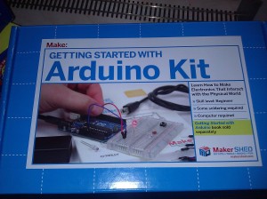
I actually got the MAKE Getting Started with Arduino Kit

MAKE Getting Started With Arduino Kit

Which opened up contained these goodies:

Arduino Kit Parts

After some reading and playing around I managed to get the light flasher portion created. I still have to design the logic around activating them and actuating a tortoise which will be used for the moving the arms up and down. In the mean time I have a picture of preliminary flasher circuit on the breadboard as well as a very short video showing them flashing.

And the video:

Netduino… totally going on my wishlist!

Electronics, Trains

I was reading through the Dawson Station blog (which is an amazing layout btw), and stumbled upon his use of Ardruino electronics for control which really intrigued me. Some searching around brought me to Netduino which is basically the same thing, but based on the .NET Micro Framework. Since I am a .NET Software Engineer this really intrigued me.

For a while I’ve really been interested in animating things on my layout such as crossing gates that actually open and close and dynamic lighting in buildings (stuff like rooms having lights turn off and on at random) or even hooking working in a fast clock and having lighting come on at “Night”. but the problem has been bridging the hardware and software gap. With Netduino being programmed in a language I use daily at work would really make it easy and fun.

That said with my limited train budget tied up for the time being I am open to accepting donations 🙂

Netduino wish list:

  1. Netduino board: http://www.netduino.com/, http://www.makershed.com/Netduino_p/mknd01.htm
  2. MakerShield kit: http://www.makershed.com/MakerShield_p/msms01.htm
  3. Breadboard supplies: (Breadboard) http://www.makershed.com/product_p/mkkn3.htm, (Jumper wires) http://www.makershed.com/product_p/mkseeed3.htm, and (Minitronics survival kit) http://www.makershed.com/Mintronics_Survival_Pack_p/mstin2.htm

Note: Shields are a term for Arduino/Netduino add on boards.